Hardware Etudes : #1 : IP Stick
IP Stick
|
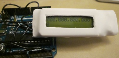
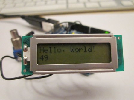
Little device for monitoring or changing IP address without need to login or connect anything else. Tiny controller with LCD Screen plus 2 buttons with USB connection placed inside heat shrunk tubing. Since it's hardware, there will be some soldering and work with inhumane acronyms, but we will try to make it as clear as possible just to get over with it. |
|
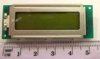
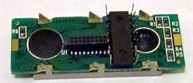
Smallest suitable LCD we were able to find was "truly mcc162c2-3" from Halted Electronics. It has a double row .05'' connector. Even if you have an adaptor from that pitch to standard .1'', it might take too much space. Solid wire #24 served us well instead. You can remove the last pair of the connectors to place the shift register even closer. Then you make a nice and clean little rat nest of wires. Later you test it with your micro-controller and seal the rat nest around the shift register with epoxy. We used a ATTiny micro-controller, since it already has numerous libraries through Arduino that deal with shift-registers, and it is of a fantastically small size.
LCD Screen pin outs, 2 kinds: one row and two rows
| 1 | Vss | Ground |
| 2 | Vdd | +5V |
| 3 | Vee |
Contrast, to potentiometer or resistors |
| 4 | Rs | Register Select |
| 5 | R/W |
Read/Write, connect to ground |
| 6 |
E |
Enable |
| 7 | D0 | |
| 8 | D1 | |
| 9 | D2 | Data bits |
| 10 | D3 | |
| 11 | D4 | In 4 bit mode |
| 12 | D5 | we will use only last 4. |
| 13 | D6 | |
| 14 | D7 |
|
2 |
+5V |
1 |
GND |
|
4 |
Rs |
3 |
Vee |
|
6 |
E |
5 |
R/W |
|
8 |
D1 |
7 |
D0 |
|
10 |
D3 |
9 |
D2 |
|
12 |
D5 |
11 |
D4 |
|
14 |
D7 |
13 |
D6 |
|
16 |
GND |
15 |
+5V |
Last pair is optional and it's for the back light.
Shift register soft and it's wiring
Shift register 74HC595 gets data through 1 wire, but also needs clock and latch wires for control. It shifts out data out on Q0-Q7 pins and holds it there. The circut between the shift register and LCD depends on the software that you will use. Arduino has number of libraries ( LCD_SPI , ShiftLCD, etc. ) but they differ in pin outs, which require a different circuit organization. But it's possible with minor tweaks in software to use the same harware with any of the Arduino libraries.
Register will shift out signals straight forward if you choose MSBFIRST in your program and do it backwards if you specify LSBFIRST. Because of this you are likely to have data output for D4-D7 pins for your LCD in right or inverse order after Rs, RW, E you use. For example you would have LSBFIRST in the ShiftLCD.h in ShiftLCD library:
// pins for functional output
#define LCD_RS_PIN 0x01 // Q7
#define LCD_EN_PIN 0x02 // Q6
#define LCD_BL_PIN 0x04 // Q5
You can change it to MSBFIRST and change Rs, RW, E pins, where the power of 2 in N ( in 0x0N notation ) is the actual number of Q pin. For example 0x01 is the Q0, 0x3 is the Q3. (And if you go backward with LSBFIRST it would be (7-power of 2))
#define LCD_RS_PIN 0x02 // Q1 pin 1
#define LCD_EN_PIN 0x08 // Q3 pin 3
#define LCD_BL_PIN 0x01 // or whatever
This will make your hardware compatible with other libraries.
74HC595 pinout and where connect to:
|
1 |
Q1 |
RS |
16 |
Vcc |
+5V |
|
|
2 |
Q2 |
15 |
Q0 |
|||
|
3 |
Q3 |
Enable |
14 |
DS |
MOSI pin #11 (#0) | |
|
4 |
Q4 |
D4 |
13 |
OE |
GND |
|
|
5 |
Q5 |
D5 |
12 |
ST_CP |
SS, latch, we used pin #9 (#1) | |
|
6 |
Q6 |
D6 |
11 |
SH_CP |
Clock, pin #13 (#2) | |
|
7 |
Q7 |
D7 |
10 |
MR |
+5V |
|
|
8 |
GND |
GND |
9 |
Q7' |
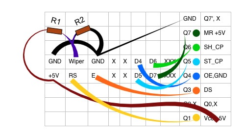
We turned the shift register upside down, so the pinouts are like this:
Connections to microcontroller will be defined in your code, you are more or less free to change them:
ShiftLCD lcd(11,13,9);//(MOSI, clock, SS)
or if you use Adafruit Trinket:
ShiftLCD lcd(0,2,1);
or if you use SPI clock and MOSI pins will be predefined by hardware:
LiquidCrystal lcd(9);
We used resistors instead of a potentiometer to regulate contrast, but either one will do fine. Our 2 resistors were 8.4K and 1K ,which ones to use are up to you.
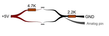
The Buttons on the analogue pins require resistors. Ours were 2.2k for pull down on the ground line, and 4.7k for one of the buttons, just so that we could tell the buttons apart.
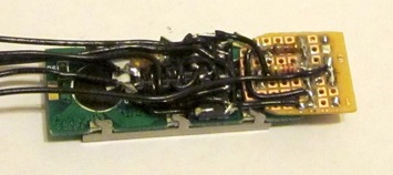
The wires are secured with a moldable epoxy, with the left side of the IP stick with room remaining for the micro-controller and USB connector. We placed it inside a 1'' heat shrunk tube and started programming.
December 28. 2014